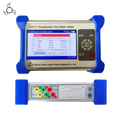
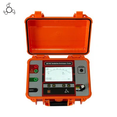
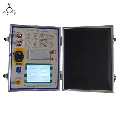
CT PT Analyzer for Substation Commissioning and Instrument Transformer Testing
The CT PT Analyzer is an automated diagnostic instrument engineered for testing current transformers (CTs) and potential transformers (PTs/VTs) in accordance with IEC 60044-1/6, IEC 61869-2, and IEEE C57.13 standards. Operating on low-frequency measurement principles, the unit determines excitation characteristics, turns ratio, polarity, winding resistance, and burden without requiring high-voltage power supplies or heavy load boxes on-site. Field engineers and manufacturing quality control teams deploy this unit to verify instrument transformer accuracy classes, knee-point voltages, and transient response parameters prior to substation grid connection or production sign-off.
-
![High Precision CT PT Analyzer]() High Precision CT PT Analyzer1.Accuracy:0.02%.. 2.Perfect performance on waterproof protection: IP67 grade.. 3.In case of connecting 220V with automatic over voltage protection function.. 4.With manual stepping, automatic
High Precision CT PT Analyzer1.Accuracy:0.02%.. 2.Perfect performance on waterproof protection: IP67 grade.. 3.In case of connecting 220V with automatic over voltage protection function.. 4.With manual stepping, automatic -
![CT PT Tester]() CT PT TesterIt has comprehensive functions, which not only meets the test requirements of excitation characteristics (V-I characteristics), ratio, polarity, secondary winding resistance, secondary load, ratio
CT PT TesterIt has comprehensive functions, which not only meets the test requirements of excitation characteristics (V-I characteristics), ratio, polarity, secondary winding resistance, secondary load, ratio


We engineer and assemble automated transformer testing systems in our 12,000-square-meter facility, maintaining direct control over internal component sourcing, signal processing PCB assembly, firmware calibration, and final burn-in testing.
Production utilizes automated surface-mount technology (SMT) lines for high-density analog acquisition boards, minimizing signal drift and thermal noise.
Every analyzer undergoes a 72-hour continuous thermal aging test at 50 degrees Celsius in an environmental chamber prior to calibration.
Core measurement modules are calibrated using national metrology-traceable reference standards with 0.005-class accuracy to ensure absolute field reliability.
Product Types
Our manufacturing line covers portable field units and automated factory test benches designed for distinct operational workflows:
Portable Field CT PT Analyzers
Rugged, enclosure-integrated units optimized for outdoor substation commissioning, featuring IP67 transport protection and internal battery/AC dual power operation.
Laboratory and Factory Test Benches
Multi-channel automated systems integrated into manufacturing lines for high-throughput batch testing of instrument transformers during production.
Multi-Functional Diagnostic Units
Combined instruments capable of executing excitation characteristics (V-I curves), remanence measurement, and instantaneous error calculations in a single automated test cycle.
Technical Specifications
| Parameter | Specification |
| Ratio Measurement Accuracy | 0.02% to 0.05% |
| Phase Accuracy Resolution | 0.1 min (0.001 deg) |
| Excitation Characteristic Test Range | Voltage output: 0 to 2,500 V; Current output: 0 to 20 A; supports knee points up to 30 kV class CTs |
| Secondary Winding Resistance Measurement | 0 to 300 ohms |
| Resistance Resolution | 0.1 milliohms |
| Burden Measurement Range | 0 to 1,000 VA |
| Burden Measurement Resolution | 0.01 ohms |
| Power Supply Input | AC 220 V +/-10%, 50 to 60 Hz |
| Power Protection | Automatic over-voltage protection |
| Data Storage Capacity | Up to 10,000 test reports |
| Data Export | USB |
| Communication Interfaces | RS232 and Ethernet |
| PC Software Integration | Supported |
| Operating Temperature Range | -10 deg C to 50 deg C |
| Enclosure Protection | IP67 with transport case closed; IP30 during operation |
Full-Auto Test Sequence
Executes ratio, polarity, excitation curve, burden, winding resistance, and error in a single automated run lasting less than 60 seconds per tap.
Low-Frequency Test Method
Replaces traditional bulky high-voltage generators and heavy loading equipment by utilizing low-frequency sweep signals to safely test high-knee-point CTs up to 30kV on-site.
Automatic Knee-Point Calculation
Internal DSP algorithms automatically extract 10% and 5% error curves, saturation voltage, and saturation current without manual graphical interpolation.
Safety Protection Circuitry
Features automatic discharge circuits, 220V misconnection protection, and primary open-circuit/secondary short-circuit fault interlocks to protect operators from high induced voltage transients.
Direct Report Generation
Generates CSV, Excel, and PDF reports directly on-screen or via thermal printer, formatted to meet international utility handover requirements.
Test Applications
Substation Commissioning and Acceptance: Routine handover testing of newly installed 35kV to 500kV GIS and AIS current and voltage transformers.
Instrument Transformer Manufacturing: Final factory quality control (QC) verification of accuracy classes (0.2S, 0.2, 0.5S, 0.5) and knee-point specifications before dispatch.
Periodic Preventive Maintenance: Annual diagnostic checks on aging substation assets to detect core degradation, turn-to-turn short circuits, or demagnetization requirements.
Metrology and Calibration Laboratories: Secondary calibration reference verification for field test kits and portable verification rigs.

How to Choose the Right Tester
For Substation Field Engineers
Prioritize portable models with IP67 rugged transit cases, lightweight form factors under 10kg, and battery-backed operation for remote switchyard locations without direct AC hookups.
For Instrument Transformer Manufacturers
Select multi-tap automated testing systems that support simultaneous multi-core winding testing and high-speed data logging to match production line output.
For High-Voltage (500kV+) Applications
Verify that the maximum output voltage of the excitation test channel exceeds the highest knee-point voltage of your target current transformers (e.g., units requiring up to 2500V output capability).
Component Traceability: All internal shunt resistors, analog-to-digital converters (ADCs), and high-voltage switching relays are sourced from verified tier-1 electronic component suppliers with strict lot traceability.
PCB Assembly: Main acquisition boards are populated on Yamaha high-speed SMT lines and subjected to automated optical inspection (AOI) to eliminate solder bridging and cold joints.
Rigorous Burn-In and Calibration: Assembled units undergo 72 hours of thermal cycling under load, followed by precision error verification across 15 calibration points against national voltage and current standards.

Customization and OEM
Firmware and Software Localization
Custom UI language packs, localized test standard profiles (IEC, IEEE, ANSI, GOST), and tailored report layout templates for regional utility requirements.
Hardware Branding
OEM casing color schemes, customized front-panel membrane overlays, and private-label documentation packages for instrument distributors and test equipment brands.
Interface Integration
Custom communication protocols (IEC 61850 or proprietary SCADA export formats) integrated into enterprise laboratory database systems.
Documentation and Certifications
Compliance Standards
Designed and manufactured in alignment with IEC 60044-1, IEC 60044-6, IEC 61869-2, and IEEE C57.13.
Shipment Documentation
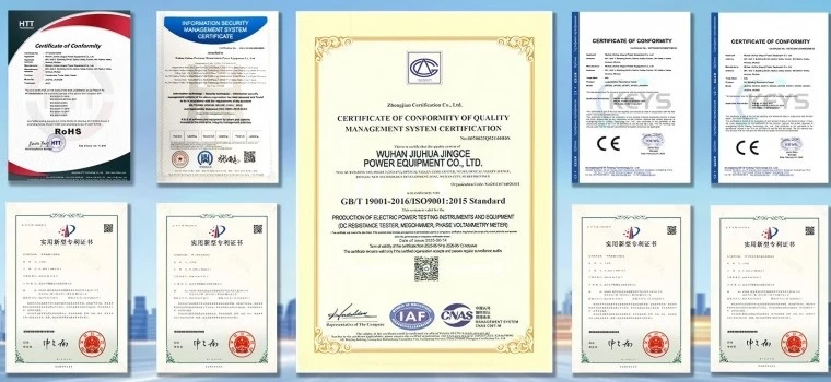
Each unit ships with an individual Factory Calibration Certificate bearing traceable metrology data, a CE conformity declaration, an electrical schematic manual, and an operation guide.
Certifications
FAQ
Q: Can this analyzer test high-knee-point CTs without external high-voltage boosters?
A: Yes. The instrument uses an advanced low-frequency test signal methodology, allowing it to evaluate CTs with knee-point voltages up to 2500V or higher using internal power sources safely within standard portable power limits.
Q: What safety mechanisms protect the operator if 220V AC is mistakenly applied to the test terminals?
A: The unit incorporates an automatic over-voltage protection circuit that isolates input channels instantly upon detecting erroneous AC mains voltage connection, preventing hardware damage and operator injury.
Q: Is it necessary to disconnect all secondary load wires during testing?
A: Yes, for accurate ratio, burden, and winding resistance measurements, the secondary winding under test must be completely isolated from external meters, protection relays, and control circuits.
Q: How is instrument calibration maintained over time?
A: The internal high-precision reference channels utilize low-drift metal-film resistors and auto-zero calibration algorithms. We recommend annual recalibration traceable to national standards, which can be performed at our factory or authorized service centers.
Q: What data export formats are supported by the operating software?
A: Test results can be exported directly as PDF reports, structured CSV files, or raw data tables via USB flash drive or transferred in real-time to a PC running our companion analysis software.
Q: Does the unit support automatic demagnetization of CT cores?
A: Yes. The test sequence includes an automatic demagnetization function executed prior to excitation and ratio testing to eliminate residual core magnetism caused by previous DC resistance measurements or fault interruptions.
Q: What is the typical lead time for standard units versus custom OEM orders?
A: Standard catalog units ship within 5 to 7 working days from stock. Custom OEM orders involving tailored firmware, specialized test standards, or private labeling typically require 3 to 4 weeks depending on volume.
As one of the most experienced ct pt analyzer manufacturers in China, we offer a wide range of products with superior quality. Please feel free to wholesale bulk durable ct pt analyzer from our factory. For price consultation, contact us.
Portable CT PT Analyzer, Automatic CT PT Analyzer, CT Analyzer