High Voltage Circuit Breaker Analyzer and HV Switch Dynamic Resistance Tester for Substation Diagnostic Testing
A high voltage switch tester (circuit breaker analyzer) measures the mechanical motion parameters, contact synchronization, operating coil characteristics, and dynamic contact resistance of high-voltage switchgear. Operating in high-voltage substations or manufacturing test bays, these instruments capture millisecond-level time intervals, stroke velocity, and micro-ohm resistance variations during open and close operations. Electrical testing engineers and utility procurement teams deploy these systems to detect mechanical wear, misalignment, or contact degradation before equipment failure occurs under load.
-
![200A Contact Resistance Tester]() 200A Contact Resistance TesterJH1006B is a high-power loop resistance tester designed for high-demand scenarios of switch control equipment. Utilizing high-frequency switching power supply and digital circuit technology, it
200A Contact Resistance TesterJH1006B is a high-power loop resistance tester designed for high-demand scenarios of switch control equipment. Utilizing high-frequency switching power supply and digital circuit technology, it -
![High Current DC Loop Resistance Tester]() High Current DC Loop Resistance TesterThe operation panel of this instrument adopts an ergonomic design that conforms to operating habits. It adopts high-frequency switching power supply and digital circuit technology, and is suitable
High Current DC Loop Resistance TesterThe operation panel of this instrument adopts an ergonomic design that conforms to operating habits. It adopts high-frequency switching power supply and digital circuit technology, and is suitable -
![200A Bluetooth Contact Resistance Tester]() 200A Bluetooth Contact Resistance TesterContact Resistance Tester is a professional high-current micro-ohm measuring instrument developed in compliance with DL/T845.4—2004 and JJG1052-2009 industry standards. Equipped with 5 gears of test
200A Bluetooth Contact Resistance TesterContact Resistance Tester is a professional high-current micro-ohm measuring instrument developed in compliance with DL/T845.4—2004 and JJG1052-2009 industry standards. Equipped with 5 gears of test -
![Upgraded Circuit Breaker Analyzer]() Upgraded Circuit Breaker AnalyzerThis instrument is a special circuit breaker analyzer developed by our company which aims to meet the needs of various high-voltage switch operating characteristics tests. It can accurately measure
Upgraded Circuit Breaker AnalyzerThis instrument is a special circuit breaker analyzer developed by our company which aims to meet the needs of various high-voltage switch operating characteristics tests. It can accurately measure -
![Gas Insulated Circuit Breaker Tester]() Gas Insulated Circuit Breaker TesterWith the development of society, people have higher and higher requirements for the safety and reliability of electricity use. High-voltage circuit breakers are responsible for the dual tasks of
Gas Insulated Circuit Breaker TesterWith the development of society, people have higher and higher requirements for the safety and reliability of electricity use. High-voltage circuit breakers are responsible for the dual tasks of -
![300A Contact Resistance Tester]() 300A Contact Resistance Tester1. The three-phase CNC sine inverter power supply output has soft start and soft stop functions, so the testing speed is fast and the accuracy is high.. 2. Three phase transformer, single-phase
300A Contact Resistance Tester1. The three-phase CNC sine inverter power supply output has soft start and soft stop functions, so the testing speed is fast and the accuracy is high.. 2. Three phase transformer, single-phase -
![Standard Contact Resistance Tester]() Standard Contact Resistance Tester1. The four-terminal wiring method effectively eliminates the influence of the resistance of the test line on the test results. 2. High test current. 3. The test current is from a high-precision
Standard Contact Resistance Tester1. The four-terminal wiring method effectively eliminates the influence of the resistance of the test line on the test results. 2. High test current. 3. The test current is from a high-precision -
![Basic Contact Resistance Tester]() Basic Contact Resistance Tester1. High current: For latest power supply technology, the tester can continuously output high current which overcomes the weakness of instantaneous current produced by pulsed power. It can effectively
Basic Contact Resistance Tester1. High current: For latest power supply technology, the tester can continuously output high current which overcomes the weakness of instantaneous current produced by pulsed power. It can effectively -
![Portable Handheld Loop Tester]() Portable Handheld Loop Tester1. The circuit resistance tester powered by lithium battery is more convenient for users. 2. Applicable to the measurement of contact resistance, loop resistance and weld contact resistance of
Portable Handheld Loop Tester1. The circuit resistance tester powered by lithium battery is more convenient for users. 2. Applicable to the measurement of contact resistance, loop resistance and weld contact resistance of -
![100A Contact Resistance Tester]() 100A Contact Resistance TesterContact resistance meter is a professional loop resistance testing instrument tailored for switch control equipment. Adopting high-frequency switching power supply and digital circuit technology, it
100A Contact Resistance TesterContact resistance meter is a professional loop resistance testing instrument tailored for switch control equipment. Adopting high-frequency switching power supply and digital circuit technology, it -
![Bluetooth 100A Contact Resistance Tester]() Bluetooth 100A Contact Resistance Tester1.Measurement range: 0-250mΩ. 2.Minimum resolution: 0.001 μ Ω. 3.Measurement accuracy: ± (reading × 0.5%+1 μ Ω). 4.Test power supply: constant current limited voltage, approximately 8.0V. 5.Test
Bluetooth 100A Contact Resistance Tester1.Measurement range: 0-250mΩ. 2.Minimum resolution: 0.001 μ Ω. 3.Measurement accuracy: ± (reading × 0.5%+1 μ Ω). 4.Test power supply: constant current limited voltage, approximately 8.0V. 5.Test -
![600A Contact Resistance Tester]() 600A Contact Resistance Tester1. Large current: This contact loop resistance tester can realize sustainable output test current from a constant current source, which overcome the malpractice of instantaneous current of the
600A Contact Resistance Tester1. Large current: This contact loop resistance tester can realize sustainable output test current from a constant current source, which overcome the malpractice of instantaneous current of the


Product Types
Multi-Channel Timing Analyzers: Configured with 3 to 12 independent timing channels to simultaneously measure main contact and auxiliary contact synchronization for three-phase high-voltage breakers.
Dynamic Contact Resistance (DCRM) Testers: Integrated high-current injection modules that measure main contact resistance continuously during the opening and closing stroke to evaluate arcing contact wear depth.
Travel and Velocity Transducer Systems: Compatible with linear and rotary optical encoders, angular sensors, and potentiometer transducers to map contact travel distance, rebound, and average closing velocity.
Dual-Coil Control Units: Measures trip and close coil current signatures, operating voltage thresholds, and coil response times to diagnose electromagnetic actuator health.
Technical Specifications
| Model Series | Timing Channels | Time Measurement Resolution | Travel Measurement Range | DCRM Output Current | Communication Interfaces |
| HVS-603 | 3 Main + 3 Aux | 0.01 ms | 0 to 1000 mm | Up to 100A DC | USB, RS232, Ethernet |
| HVS-612 | 12 Main + 6 Aux | 0.005 ms | 0 to 1200 mm | Up to 200A DC | Ethernet, USB, Wi-Fi |
| HVS-DCRM | 6 Main + 6 Aux | 0.005 ms | 0 to 1000 mm | Up to 300A DC | Ethernet, USB, Modbus |
| HVS-PORT | 3 Main + 3 Aux | 0.02 ms | 0 to 500 mm | N/A (Timing only) | USB, RS232 |
| Parameter | Specification |
| Input Power | AC 220 V +/-10%, 50/60 Hz; internal rechargeable lithium-ion battery pack |
| Battery Operating Capacity | Up to 8 hours |
| Operation Modes | Single close, single open, open-close, close-open, and O-C-O sequence testing |
| Anti-Interference Protection | Built-in strong electric field shielding for reliable operation in 500 kV live switchyards |
| Operating Temperature | -20 deg C to +50 deg C |

Strong Magnetic Field Shielding: Integrated hardware filtering circuits and grounded aluminum chassis suppress electromagnetic interference, enabling stable testing in live 500kV switchyards without false triggering.
High-Speed Sampling Architecture: Employs high-frequency 100 kHz analog-to-digital converters to capture precise microsecond-level contact bounce and parting synchronization data.
Automatic Travel Calibration: Software wizard automatically scales linear and rotary transducer inputs based on physical stroke parameters, eliminating manual calculation errors.
Intelligent Trip Coil Monitoring: Simultaneously records coil voltage and dynamic current curves to identify mechanical binding or shorted turns in operating mechanisms.
On-Board Diagnostic Analysis: Embedded industrial processor generates automatic pass/fail evaluation reports against preset manufacturer threshold parameters directly on the 10.4-inch sunlight-readable touch display.
Test Applications
Substation Commissioning
Verifies mechanical timing and synchronization of newly installed GIS (Gas-Insulated Switchgear) and SF6 circuit breakers prior to grid connection.
Preventive Maintenance Outages
Evaluates arcing contact degradation and mechanical wear during scheduled annual maintenance in transmission substations.
Switchgear Manufacturing Quality Control
Conducts routine mechanical characteristic tests on factory assembly lines to verify manufacturing tolerances and contact alignment.
Failure Investigation
Analyzes trip current signatures and contact travel profiles following unexpected breaker trip events or mechanism failures.

How to Choose the Right Tester
Determine Pole and Channel Count
Select 3-channel units for single-phase or independent pole testing, or 12-channel units for simultaneous three-phase circuit breaker testing with auxiliary contact monitoring.
01
Evaluate DCRM Necessity
Choose models with built-in Dynamic Contact Resistance Measurement (DCRM) if your maintenance protocol requires evaluating arcing contact wear without disassembling the interrupter chamber.
02
Assess Field Environment Requirements
Select battery-powered, ruggedized portable units for remote outdoor substation deployment, or high-end multi-channel cabinet units for automated manufacturing test bays.
03
Review Software and Reporting Standards
Ensure the instrument software generates exportable data formats compatible with utility asset management systems and standard IEC/IEEE test report templates.
04
Circuit Board Assembly: Surface-mount controller boards are assembled on automated SMT lines, followed by automated optical inspection and thermal aging chambers at +60 deg C for 72 hours.
Transducer Calibration Rig: Every linear and rotary displacement sensor is calibrated against laser interferometer reference benches to guarantee linear accuracy within +/-0.05 mm.
High-Voltage Isolation Testing: Main measurement input terminals undergo 2kV dielectric withstand testing against the instrument chassis to ensure operator safety during high-induction transients.
Final Metrology Audit: Complete analyzers are tested using synchronized mechanical simulation rigs to verify timing accuracy across all channels before calibration certificates are issued.

Customization & OEM
Language and Standard Localization
Custom user interface languages, localized software menus, and firmware presets matching specific regional utility testing standards (IEEE C37, IEC 62271).
Enclosure Hardening
IP67-rated waterproof Pelican transport cases or custom 19-inch rack-mount configurations for mobile testing laboratories.
Specialized Sensor Tooling
Design and fabrication of custom mechanical mounting brackets and magnetic attachment arms for non-standard circuit breaker linkage geometries.
OEM Private Labeling
Brand color customization, startup logo integration, and custom documentation packaging for instrument distributors.
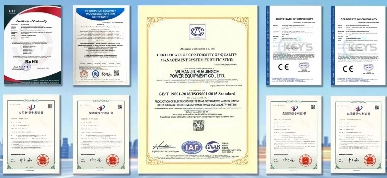
Documentation & Certifications
Compliance Standards
Manufactured in strict accordance with IEC 62271-100, IEC 61010-1, and IEEE C37.09 standards for high-voltage switchgear testing equipment.
Certifications
CE marked, EMC Directive compliant, and supplied with ISO/IEC 17025 traceable calibration certificates.
Shipped Documentation
Each unit includes a printed English operational manual, transducer mounting guide, calibration report, grounding cable, and utility analysis software on USB drive.
Certifications
FAQ
Q: How does the tester prevent false readings in live high-voltage switchyards?
A: The instrument utilizes optical isolation on all signal inputs, differential analog sampling circuits, and a heavy-gauge grounded aluminum chassis to suppress electromagnetic induction, ensuring accurate data capture even when testing in proximity to energized 500kV busbars.
Q: Can the instrument measure dynamic contact resistance without dismantling the breaker?
A: Yes. By injecting a high DC current up to 300A through the breaker contacts while recording voltage drop and travel distance simultaneously, the tester generates a resistance profile that reveals arcing contact wear depth without opening the SF6 interrupter chamber.
Q: What is the maximum travel measurement range for rotary actuators?
A: Standard rotary transducers accommodate angular rotation up to 360 degrees with 0.1-degree resolution, while linear transducers support stroke lengths up to 1200 mm, covering most distribution and transmission class circuit breakers.
Q: How are travel transducers mounted on closed circuit breakers?
A: Magnetic mounting bases and adjustable telescopic extension arms allow quick mechanical coupling to the breaker moving operating rod or indicator linkage without requiring custom drilling or permanent fixture modification.
Q: What data export formats are supported by the analysis software?
A: Test results, travel curves, and current signatures can be exported directly as PDF test reports, Excel spreadsheets, or raw data files for integration into enterprise utility asset management databases.
Q: What is the standard lead time for standard versus customized units?
A: Standard catalog models ship within 7 to 10 business days. Custom hardware configurations, specialized sensor brackets, or localized software adaptations require 3 to 4 weeks depending on technical requirements.
Q: What warranty coverage and technical support are included?
A: All units include a 2-year standard manufacturer warranty covering parts and workmanship, supported by remote engineering diagnostics, annual calibration services, and firmware update support.
As one of the most experienced hv switch tester manufacturers in China, we offer a wide range of products with superior quality. Please feel free to wholesale bulk durable hv switch tester from our factory. For price consultation, contact us.