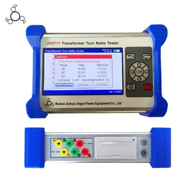
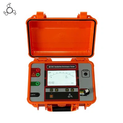
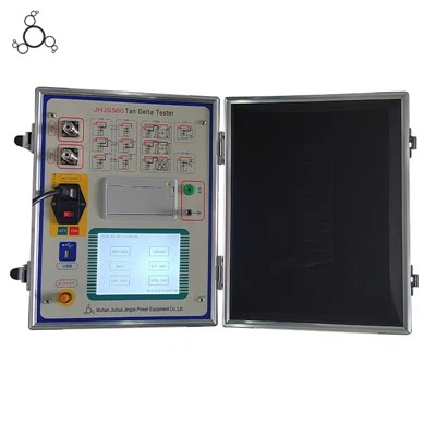
Secondary Current Injection Testing Equipment for Substation Relay Protection and Commissioning
The Secondary Current Injection Testing Equipment is a portable diagnostic instrument engineered for functional testing, calibration, and troubleshooting of protective relays, meters, and trip control circuits in electrical substations. By injecting programmable multi-phase current and voltage signals directly into protection panels, the unit verifies pickup thresholds, operating times, and tripping logic without primary high-voltage application. Electrical testing engineers and switchgear manufacturers deploy this system to validate relay coordination and ensure fault-clearing reliability across industrial and utility power networks.
-
![Microcomputer Three Phase Relay Protection Tester]() Microcomputer Three Phase Relay Protection TesterThe instrument has standard four-phase voltage, three-phase current output, classic Windows XP operating interface, high-performance embedded industrial control computer and 10.4 inch resolution of
Microcomputer Three Phase Relay Protection TesterThe instrument has standard four-phase voltage, three-phase current output, classic Windows XP operating interface, high-performance embedded industrial control computer and 10.4 inch resolution of -
![Secondary Current Injection Tester]() Secondary Current Injection TesterMain Features:. (1)Single Phase Current Output:Single Phase Current Output. (2)Three Phase Parallel Output:Three Phase Parallel Output. (3)Max Output Power Per Phase:400 VA. (4)Frequency Range:0 ~
Secondary Current Injection TesterMain Features:. (1)Single Phase Current Output:Single Phase Current Output. (2)Three Phase Parallel Output:Three Phase Parallel Output. (3)Max Output Power Per Phase:400 VA. (4)Frequency Range:0 ~ -
![120A Three Phase Relay Protection Tester]() 120A Three Phase Relay Protection TesterJHS804 is a professional three-phase relay tester and dedicated secondary current injection test device designed for power system protection debugging, featuring 4-phase voltage (125V/phase) and
120A Three Phase Relay Protection TesterJHS804 is a professional three-phase relay tester and dedicated secondary current injection test device designed for power system protection debugging, featuring 4-phase voltage (125V/phase) and -
![High Precision Relay Protection Tester]() High Precision Relay Protection TesterS903 is an industrial control type three-phase relay protection tester for 10KV/35KV and below protection debugging. It features four-phase voltage and three-phase current output, 10.4-inch true
High Precision Relay Protection TesterS903 is an industrial control type three-phase relay protection tester for 10KV/35KV and below protection debugging. It features four-phase voltage and three-phase current output, 10.4-inch true -
![Portable Phase Relay Protection Tester]() Portable Phase Relay Protection TesterClassic Windows XP operating interface, friendly man-machine interface, easy and fast to operate; High-performance embedded industrial control computer and 8.4 inch resolution of 800 × 600 TFT true
Portable Phase Relay Protection TesterClassic Windows XP operating interface, friendly man-machine interface, easy and fast to operate; High-performance embedded industrial control computer and 8.4 inch resolution of 800 × 600 TFT true -
![Six Phase Relay Protection Tester]() Six Phase Relay Protection TesterJHS1300 is a professional six-phase relay protection tester and dedicated secondary injection testing equipment designed for power system protection debugging, featuring 6-phase voltage (125V/phase)
Six Phase Relay Protection TesterJHS1300 is a professional six-phase relay protection tester and dedicated secondary injection testing equipment designed for power system protection debugging, featuring 6-phase voltage (125V/phase) -
![Industrial Six Secondary Current Injection Testing Equipment]() Industrial Six Secondary Current Injection Testing EquipmentJHT1200 is a professional microcomputer relay protection tester with 6-phase voltage and 6-phase current output, designed for 10KV/35KV and below power system protection debugging. It features a
Industrial Six Secondary Current Injection Testing EquipmentJHT1200 is a professional microcomputer relay protection tester with 6-phase voltage and 6-phase current output, designed for 10KV/35KV and below power system protection debugging. It features a


We engineer and assemble automated electrical test instrumentation in our 12,000-square-meter production facility, maintaining direct control over multi-channel digital signal processor (DSP) board fabrication, linear amplifier assembly, firmware flashing, and thermal burn-in.
Signal acquisition and amplification boards are populated using automated surface-mount technology (SMT) lines to eliminate thermal drift and signal cross-talk.
Every testing unit undergoes a 72-hour continuous full-load burn-in test at 45 degrees Celsius in an environmental testing chamber.
Analog output channels are calibrated against national metrology-reference standards with 0.05-class precision to ensure absolute field measurement traceability.
Testing Capabilities and Product Types
Portable 3-Phase or 6-Phase Relay Testers
Rugged, enclosure-integrated units optimized for outdoor substation commissioning, featuring AC/DC power operation and transient fault playback capability.
Switchgear Factory Test Benches
Multi-rack automated testing systems integrated into manufacturing floors for rapid batch verification of low-voltage control and protection panels.
Specialized Metering Test Kits
Dedicated units configured for high-accuracy calibration of static electricity meters, energy transducers, and phasor measurement units (PMUs).
Technical Specifications
| Parameter | Specification |
| AC Current Output Channels | 3 or 6 channels |
| AC Current Output Range | 0 to 30 A per channel; parallel connection up to 180 A |
| DC Current Output Range | 0 to 10 A per channel |
| AC Voltage Output Channels | 4 channels |
| AC Voltage Output Range | 0 to 120 V phase voltage; line voltage up to 300 V |
| Output Accuracy | Current and voltage error less than 0.05% of reading + 0.02% of range |
| Harmonic Distortion (THD) | Less than 0.1% at rated resistive load |
| Phase Angle Range | 0 to 360 degrees |
| Phase Angle Resolution | 0.01 degrees |
| Frequency Range | DC, 10 Hz to 1,000 Hz |
| Harmonic Generation | Up to the 20th harmonic order |
| Binary Inputs | 8 channels; potential-free or 24 V to 250 V DC sensed |
| Binary Outputs | 4 binary relay outputs |
| Power Supply Input | AC 220 V +/-10%, 50 to 60 Hz |
| Power Protection | Automatic thermal overload cutoff |
| Enclosure Protection | IP65 with transport case closed; IP30 during operation |
High-Linearity Power Amplifiers: Utilizes direct-coupled linear power amplification modules to maintain low harmonic distortion and high signal fidelity when driving inductive relay coils.
Transient Fault Simulation: Supports COMTRADE file playback to replicate real-world fault waveforms, voltage sags, and frequency swings recorded by digital fault recorders (DFRs).
Automated Test Template Execution: Pre-configured test modules execute multi-step characteristic curves (overcurrent, directional, distance, differential) without manual intervention.
Comprehensive Protection Circuitry: Built-in hardware interlocks protect output channels against open-circuit voltage spikes, short circuits, thermal overload, and misapplied external DC supplies.
Standalone Operation Interface: Equipped with a high-contrast industrial touchscreen and embedded real-time OS, allowing full manual testing without requiring an external laptop in the field.

Test Applications
Substation Acceptance Commissioning: Pre-energization verification of numerical protection relays (overcurrent, earth fault, busbar, and transformer differential protection) in GIS and AIS substations.
Routine Preventive Maintenance: Periodic verification of relay pickup settings, trip contact timing, and auxiliary lockout functions during scheduled annual utility outages.
Switchgear Panel Manufacturing (FAT): Final factory quality control (QC) testing of assembled control and protection relay cabinets before shipping to customer sites.
R&D and Type Testing: Laboratory evaluation of prototype protection algorithms and electromagnetic compatibility (EMC) response under distorted wave conditions.

How to Choose the Right Tester
For Distribution Substation Field Engineers
Choose 3-phase current and 4-phase voltage portable test sets, which provide sufficient power to test standard overcurrent, voltage, and directional protection schemes efficiently.
WFor Transmission and Generation Protection
Prioritize 6-phase current output models capable of executing complex transformer differential testing and multi-terminal line distance protection evaluations.
For Switchgear Panel Manufacturers
Select robust, rack-mountable or trolley-integrated test units supporting high duty cycles and rapid automated test sequence scripting for production lines.
Manufacturing and Quality Control
Component Traceability
All precision digital-to-analog converters (DACs), high-speed switching transistors, and isolation transformers are sourced from verified tier-1 electronic component manufacturers with strict batch tracking.
PCB Assembly and Inspection
Main control and amplifier boards undergo automated optical inspection (AOI) and X-ray inspection on SMT lines to ensure solder joint integrity under high-vibration transport.
Precision Calibration Routine
Final verification maps output linearity across 20 distinct load points, ensuring that thermal drift remains within tolerance limits during extended test sessions.
Customization and OEM
Software and Language Localization
Custom UI language packs, localized test standard profiles (IEC, IEEE, ANSI, GB), and tailored report templates matching regional utility formats.
Hardware Branding
OEM chassis color schemes, custom front-panel overlays, and private-label technical documentation for instrument distributors and test gear brands.
Communication Protocols
Integration of specific SCADA or substation automation protocol simulators (such as IEC 61850 Sampled Values and GOOSE messaging test capabilities) upon request.
Documentation and Certifications
Compliance Standards
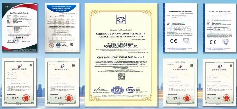
Designed and manufactured in strict alignment with IEC 60255, IEC 61010-1, and electromagnetic compatibility standards IEC 61326-1.
Shipment Documentation
Each testing unit is shipped with an individual Factory Calibration Certificate containing traceable metrology data, a CE conformity declaration, a wiring schematic manual, and an operation guide.
Certifications
FAQ
Q: Can this tester evaluate modern microprocessor-based numerical relays from major manufacturers?
A: Yes. The unit is fully compatible with numerical, static, and electromechanical relays produced by major global brands, supporting standard communication inputs and binary signal handshaking.
Q: Does the equipment support IEC 61850 digital substation testing?
A: Yes. Select models feature optical Ethernet ports supporting IEC 61850-9-2 Sampled Values (SV) and GOOSE message publishing/subscribing for direct testing of digital substation merging units and protection IEDs.
Q: What protection mechanisms prevent damage if the output current terminals are short-circuited?
A: The internal amplifier stages incorporate real-time electronic current limiting and thermal shutdown sensors that instantly trip output signals upon detecting an unintended short circuit or overload condition.
Q: Is it necessary to connect a laptop computer to operate the test set during field commissioning?
A: No. The unit features an integrated industrial display and onboard software interface that permits complete manual and automated test execution directly from the front panel.
Q: How is long-term measurement accuracy maintained?
A: The internal reference channels utilize low-drift, precision wire-wound resistors and software auto-calibration algorithms. Annual calibration traceable to national standards is recommended and can be performed at our factory or authorized service centers.
Q: What test report formats are generated by the software?
A: Test results, including pass-fail evaluations, characteristic curves, and raw data logs, can be exported directly as structured PDF reports or editable CSV files via USB flash drive.
Q: What is the standard lead time for standard units versus custom OEM orders?
A: Standard catalog units ship within 5 to 7 working days from stock. Custom OEM projects involving specialized enclosure designs, localized software profiles, or private labeling typically require 3 to 4 weeks depending on order volume.
As one of the most experienced secondary current injection testing equipment manufacturers in China, we offer a wide range of products with superior quality. Please feel free to wholesale bulk durable secondary current injection testing equipment from our factory. For price consultation, contact us.
secondary current injection testing equipment, Relay Protection Tester, Microcomputer Three Phase Relay Protection Tester